It is insanely fast, even a maverick will agree! And, it is equally fattish than the all known preceding transports technologies given that a 1 RU switch can now pack a whopping 12.8 Tbps bandwidth: get the picture?
Welcome to the world of terabit transport!
Target for massive aggregation in data center and service provider networks, 400 Gigabit Ethernet (400GbE) was approved as IEEE802.3bs standard on December 6, 2017. The 400GbE standardization marks a milestone towards 1 Tbps per port speed. With Chip vendors keeping up their game, 400GbE is now available in per port speed at 1 RU form factor and in chassis form factor. For a standard 32 ports 400 GbE 1 RU switch such as Delta’s Agema® AGC032, total bandwidth is whopping 12.8tbps. At chassis level, a combination of chips could provide service provider an option of upto 1 Pbps (Petabit per Second) system. To put in perspective, 1 Pbps is nearly thousand times bandwidth of 1 terabit system. That’s about breaking the barrier: like 5,000 two-hour-long HDTV videos in one second (Sverdlik, 2015).
Secrete ingredients of whopping speed
Sounds mind boggling! It should not be, advances in silicons made it possible for a combination of chips to support Petabits system. As for 400GbE Systems, the fundamental block of data interchange speed is 50Gig per second (50Gbps) run through 8 lanes to give a speed of 400GbE [50Gbits x 8] per port. This basic block of data interchange is known as SerDes (Serializer/Deserializer). In 100GbE, 4 lanes of 25Gbps SerDes are implemented to achieve 100GbE speed. Depending upon SerDes implementation, speed for each SerDes may varies, e.g. a 25G SerDes may have speed upto 26.56G. The diagram below depicts SerDes speed and lanes respectively for each type of link speed. For example, 10GbE uses a SerDes with single lane for 10G and 40G link speed uses 4 lanes of 10G SerDes to acheive 40GbE and so on. When 100G SerDes will be developed, such SerDes with 8 channels can achieve 800GbE link speed.

Figure 1. A diagrammatical representation of lanes and speed of SerDes that help achieve port speed of an Ethernet Switch.
The IEEE Standard
As stated earlier, IEEE802.3bs specifies requirements for 400Gig Ethernet implementation. The following diagram depicts typical vendor specific implementation of “400GbE layered architecture” of IEEE802.3bs. A semiconductor vendor may choose to implement IEEE802.3bs architecture in two chips or in a single chip [please refer diagram below]. The single chip implementations are most popular and silicon that offers such solution with additional software features are known as SoC (System on Chip). The sublayers specified in IEEE802.3bs architecture is drawn from original 802.3 std and subsequent revisions thereof for 1/10/100GbE. For those who are not familiar with sublayers of IEEE802.3 architecture, I am providing a brief herein below:
- MAC (Medium Access Control): A sublayer for framing, addressing and error detection.
- RS (Reconciliation Sublayer): It provides interfaces to Ethernet PHY.
- PCS (Physical Coding Sublayer): The PCS is used for coding (64B/66B), lane distribution, EEE functions.
- PMA (Physical Medium Attachment): This sublayer provides Serialization, clock and data recovery.
- PMD (Physical Medium Dependent): It is a physical interface driver.
- MDI (Medium Dependent Interface): It describes interface for both physical and electrical/topical from physical layer implementation to physical medium.
The sublayer of CDMII is not implemented and reserved for future use for which physical instantiation in not needed (D’Ambrosia, 2015).

Figure 2. A comparative outlook of IEEE802.3bs layered architecture of 400GbE and vendor specific implementation of 400GbE.
What’s in a box?
A typical SoC can packed up enough horse power to support more than 12 tbps of bandwidth for a 32 ports 1 RU switch. For example, Delta’s Agema® AGC032 supports upto 12.8tbps for 32 x 400GbE switch (please refer the figure below).
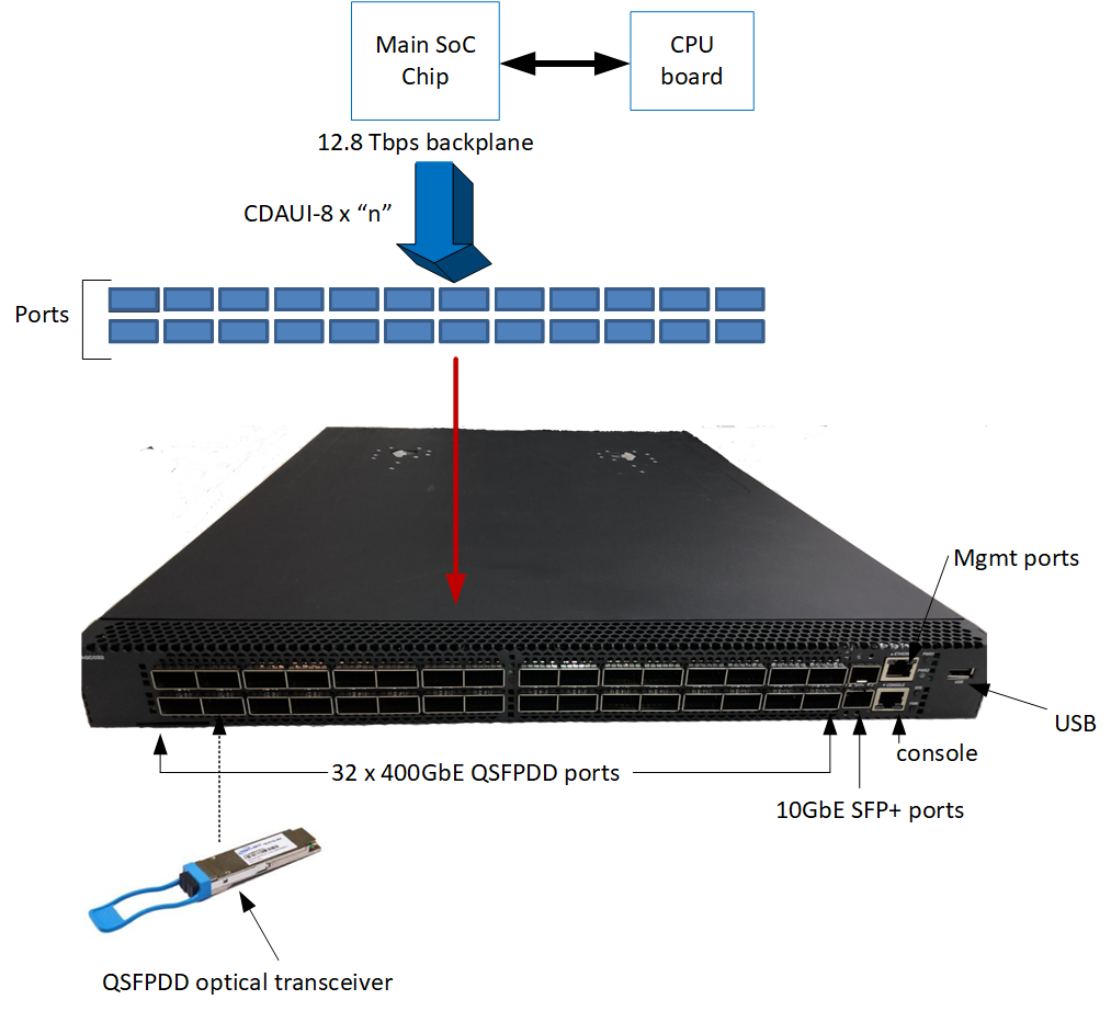
Figure 3. Agema® AGC032 12.8tbps 32 ports 400GbE whitebox switch.
Such design generally needs densely packed front panel ports and uses QSFP-DD form factor of optical transceivers for link level transport. The QSFP-DD expands QSFP/QSFP28 (an optical pluggable module commonly used in 40GbE and100GbE respectively) from four lanes electrical signals to eight lane signals. The QSFP-DD MSA group defines the specification for QSFP-DD. If you need further details on qsfp-dd, please download the specification from http://www.qsfp-dd.com/specification/ (QSFP-DD MSA, 2017). The QSFP-DD specification (QSFP-DD MSA, 2017) defines power classes for upto 14 Watts for single QSFP-DD module, however depending upon cage and module design power consumption may vary (please refer to table 5 and 6 of QSFP-DD specification for further details). Similar to QSFP-DD, other MSA (Multi-source Agreement) groups are also working on optical module specification for 400G and a list of them are given below. Please note, MSA is not a standard group rather an interest group comprised of optical transceiver vendors that often specifies form factor and electrical interface for optical modules.
MSA groups that are working on 400G optical modules:
- CFP (C Form-factor Pluggable) at http://www.cfp-msa.org/ .
- OSFP (Octal Small Form Factor Pluggable) at http://osfpmsa.org/
- COBO (Consortium for On-Board Optics): http://onboardoptics.org/ The Interconnects
The Interconnects
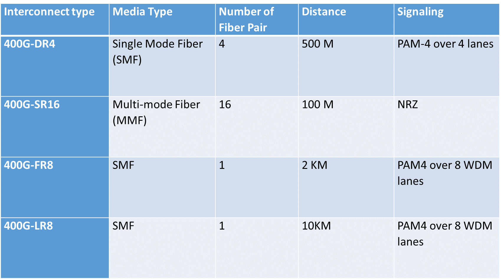
400GbE supports four different types of transceivers: 400G-DR4, 400G-SR16, 400G-FR8 and 400G-LR8. The following table depicts particulars for each type of interconnect.
Table 1. 400G Interconnect types, distance limit and signaling requirements.
Typical Deployment
400G Ethernet Switches can be deployed in various configurations in Data Centers for Super Spine in a five folded Clos, Data Center Interconnect (DCI), Telecom Networks for aggregation and IXCs for transport peering etc. The following diagrams shows some typical deployments.
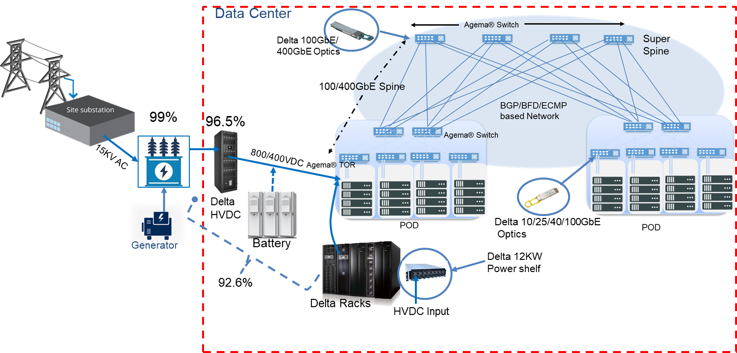
Figure 4. Typical deployment of 400G Whitebox Switch (e.g. Agema® AGC032) in super spine for Data Center Clos architecture.
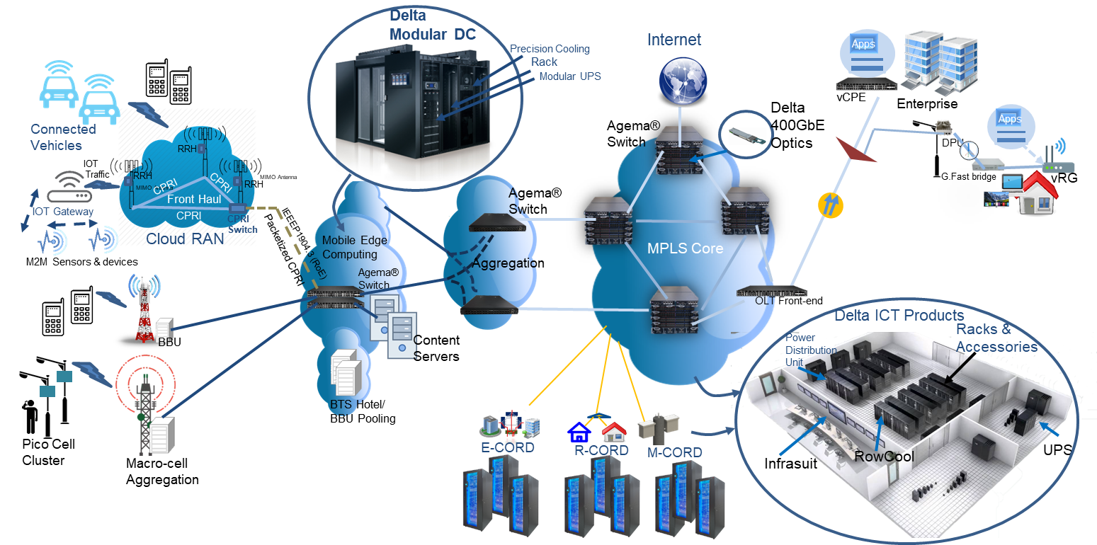
Figure 5. Typical deployment of 400G in edge aggregation at telecom networks.
For distance over 10km, 400G deployment may need to use transponder and ROADM for better transport distribution on a dark fiber. Hopefully, distance limitation can be overcome with new optical transceivers for upto 100km in near future. However, transponders and ROADM will be necessary for distance beyond 100km and even for sharing single fiber at lower distance.
Conclusion
Welcome to the world of terabit transport. 400GbE is a great step towards terabit per port transport capabilities and given that whitebox switch is offering such possibilities at a better price, data centers and service providers are now able to build infrastructure for future payloads. Hence, addressing bandwidth demands would not be issue. With significant CAPEX and OEPX reduction offered by whitebox switches, service providers and hyperscale data center now can focus on more service offerings for what future holds.
Reference:
- Sverdlik, Y. 2015. Custom Google Data Center Network Pushes 1 Petabit Per Second. DataCenter Knwloedge. Avilable online at http://www.datacenterknowledge.com/archives/2015/06/18/custom-google-data-center-network-pushes-1-petabit-per-second
- D’Ambrosia, 2015. IEEE P802.3bs Baseline Summary: Post July 2015 Plenary Summary. Available online at http://www.ieee802.org/3/bs/baseline_3bs_0715.pdf .
- QSFP-DD MSA, 2017. QSFP-DD Hardware Specification for QSFP DOUBLE DENSITY 8X PLUGGABLE TRANSCEIVER. Available at http://www.qsfp-dd.com/wp-content/uploads/2017/09/QSFP-DD-Hardware-rev3p0.pdf
Comments